Vis Raw Frame Product
Data product name
DpdVisRawFrame
Data product custodian
Name of the Schema file
euc-le1-VisRawFrame.xsdDPDD version
1.1
Processing Element(s) creating/using the data product
Creators:
LE1_VIS
Consumers:
VIS_PF
Processing function using the data product
VIS processing function.
Data product elements
- Header:
object of type sys:genericHeader
- Data:
object of type le1vis:visRawFrame
- QualityFlags:
object of type dqc:sqfPlaceHolder
- Parameters:
object of type ppr:genericKeyValueParameters
Detailed description of the data product
The LE1-VIS component of the LE1 processing function provides calibration and scientific exposures and the associated metadata.
Calibration and scientific exposure is provided as one multi-extension FITS (MEF) file, with one extension per quadrant, that is 144 extensions altogether.
The CCD numbering and location on the detector plane is showed on Fig. 6 and Fig. 7 below. The dotted circles are attachements of the CDD packages.
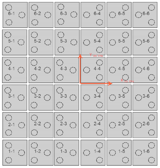
Fig. 6 : CCD numbering and location at detector plane level (Front view) From VIS FPA ICD (EUCL-SAP-ICD-6-001) issue 2.5 2014/20/10
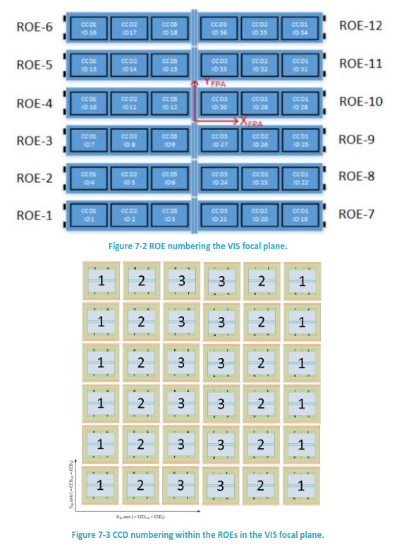
Fig. 7 : CCD numbering and location at detector plane level (Front view) From VIS FPA ICD (EUCL-SAP-ICD-6-001) issue 5.1 2020/10/23
One can notice that CCDs on the right side of the focal plane are rotated by 180° with respect to those on the left. This means that CCD quadrants are not positioned the same way across the FPA, as showed on the Fig. 8 below for CCD 1-3 and 1-4.
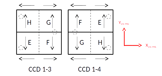
Fig. 8 : Quadrant position on the FPA
Fig. 9 below shows one CCD with the position of the 51 pre-scan and 20 over-scan pixels with respect to the imaging area. Each quadrant is marked with either E, F, G or H, according to the naming used by the manufacturer.
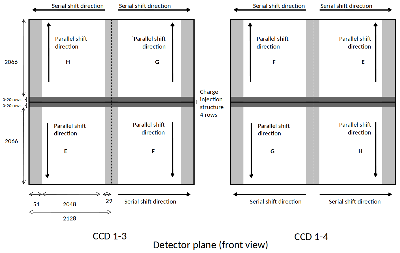
Fig. 9 : Quadrant organisation in a CCD
Note: the charge injection structure which is four rows in the middle of the CCD: this will create a gap in the images.
Data encoding
All pixel data are in units of ADU, 16-bit unsigned integer.
The origin of each data array is located at the bottom left of the FPA with respect to Fig. 6. The following Fig. 10 shows the origin of the data array and NAXIS1, NAXIS2 axes for each quadrant in a CCD.
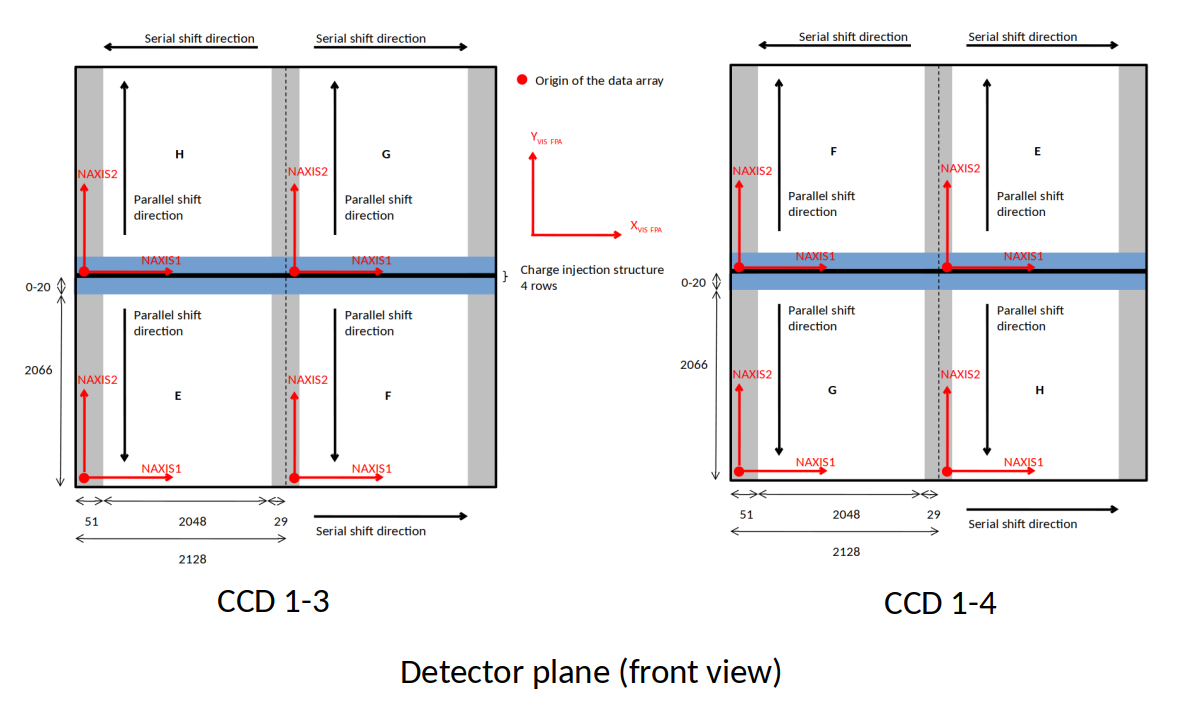
Fig. 10 : FITS data array organisation for each quadrant in a CCD
Header content
Primary header
Extension headers
Each extension shall contain the CCD and quadrant identification. CCD will be identified with the numbering shown above (‘1-1’, ‘1-2’,…, ‘6-6’) and the quadrant by the letters ‘E’, ‘F’, ‘G’ or ‘H’ according to Fig. 9.
On the next LE1 PF release, these two keywords value will be modified or added:
Predicted / instantaneous spacecraft velocities in TBD referential:
The spacecraft instantaneous velocity will be used to correct the velocity aberration (astrometric effect which produces an apparent displacement of celestial objects about their true positions, dependent on the velocity of the observer). In case the instantaneous spacecraft velocities were not available in time to be included in the LE1 data product we would use a predicted velocity to apply a first approximative correction that will be refined afterwards with the instantaneous value.
Temperatur of the CCD check with VIS IDT that this data is available as such (which temperature sensors are there, which data will be available on ground?).
Temperature of the telescope.
File checksum.