NISP Raw Frame Product
Data Product Name
DpdNispRawFrame
Data Product Custodian
Name of the Schema File
euc-le1-NispRawFrame.xsdLast Edited for DPDD Version
1.1
Processing Elements Creating / Updating / Using the Product
Creators:
LE1 NISP Processor
Consumers:
NIR, SIR, SOC AUX Processor, SOC QLA, IODA
Processing Function using the products
LE1
Data Product Elements
- Header:
object of type sys:genericHeader
- Data:
object of type le1nisp:nispRawFrame
- QualityFlags:
object of type dqc:sqfPlaceHolder
- Parameters:
object of type ppr:genericKeyValueParameters
Detailed Description of the Data Product
A NISP raw exposure provides calibration, engineering and scientific exposures acquired by the NISP instrument, together with the associated metadata, for each supported exposure configuration mode.
The following table summarizes the NISP instrument exposure configurations and the corresponding raw data sections available in the files produced by the on-board Data Processing Unit (DPU):
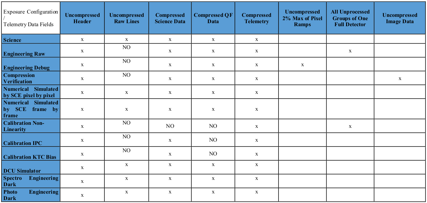
Fig. 3 : NISP exposure configurations and corresponding data sections
Depending on the exposure configuration, three types of FITS files can be produced and referenced by a single DpdNispRawFrame data product:
NISP frame: it is a sngle multi-extension FITS file, with FitsFormat id = “le1.nispRawImage”, containing two extensions per detector; one extension is an image containing the detector scientific data, while a second extension provides the detector Chi2 data. Hence the file can contain up to 32 extensions. The Chi2 data content depends on the instrument channel: for photometric exposures, it provides a quality value {0,1} computed on-board, while for the spectroscopic channel it includes the full Chi2 value (8-bit integer).
HK raw data: it is a single multi-extension FITS file, with FitsFormad id = “le1.nispHkRaw”, which includes housekeeping information extrated from the raw DPU file, including digital telemetry, raw lines for each detector, analog telemetry, error buffer and history data (see the NISP Instrument Flight User Manual Document, section 14.1).
Engineering exposures: it is a list of FITS files, with FitsFormat id = “le1.nispEngExposure”. Each file includes one or more image HDUs. The meaning and structure of these images depend on the specific engineering mode (raw or debug) configured for the exposure acquisition.
NISP Frame FITS format
Each NISP exposure is provided as one multi-extension FITS (MEF) file. In particular, the file contains two extensions per detector: one extension for the detector scientific data, and one extension for the detector Chi2 data (quality factor). Depending on the number of detectors acquired, the file can contain up to 32 extensions. Tipically, the engineering model of the instrument only has few detectors connected, while the flight model provides all 16 detectors.
The detectors numbering and location on the NISP Detector System Assembly is shown in Fig. 4 below
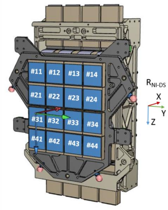
Fig. 4 : NISP Detector System Assembly: detectors position and ID
Within each Sensor Chip Array (SCA), the pixel (0,0) is located on the upper left corner when seeing the front side of the SCA with their wire bounding located on top. Consequently, pixel (0,0) is located:
on the upper left corner in the detectors:
#11, #12, #13, #14
#21, #22, #23, #24
on the lower right corner in detectors:
#31, #32, #33, #34
#41, #42, #43, #44
This is shown in Fig. 5
Fig. 5 : Pixel layout of the different SCAs
Each SCA contains both reference pixels and science pixels. Reference pixels are located all around the detector. The science pixels are located in the central window:
(xcorner, ycorner, xsize, ysize) = (3, 3, 2040, 2040)
Data encoding
For each detector:
pixels in the scientific extension are in units of ADU, 16-bit unsigned integer.
pixels in the Chi2 extension only provides a single bit of information for the photometric observations, and an integer value for the spectroscopic observations. In both cases the values are stored as an 8-bit unsigned integer.
Primary header
FITS_DEF |
le1.nispRawImage |
/ |
FITS definition name |
FITS_VER |
1.0 |
/ |
FITS definition version |
TELESCOP |
Euclid |
/ |
|
INSTRUME |
NISP |
/ |
or NISPsim for simulations |
VERSION |
/ |
Data Release version |
|
DATE |
/ |
UT date when this file was created |
|
ORIGIN |
/ |
FITS file originator |
|
OBASW |
/ |
On board application software version (NISP DPU SW version) |
|
SOFTVERS |
/ |
Version of the processing function |
|
AUX_VERS |
/ |
Version of the AUX Processor |
|
OBT-OBS |
/ |
On-Board Time of the observation (start), e.g. ‘2014-03-15T09:30:09.313’ |
|
OBT_STA1 |
/ |
Integer, number of seconds of OBT (START_TIME) |
|
OBT_STA2 |
/ |
Integer, number of microseconds of OBT (START_TIME) |
|
DATE-OBS |
/ |
UTC Date of observation (start), e.g. ‘2014-03-15T09:30:09.313’ |
|
MJD-OBS |
/ |
MJD start time, e.g. 56731.39594113 |
|
DATE_AUX |
/ |
ISO-format timestamp when AUX Processor has added additional metadata |
|
IMG_CAT |
/ |
DP category (SCIENCE, CALIB, …) |
|
IMG_T1 |
/ |
DP type (OBJ, SRD, DARK, …) |
|
IMG_T2 |
/ |
DP type (LAMP, SKY, …) |
|
OBSTYPE |
/ |
DP technique (IMAGE, SPECTROIMAGE) |
|
OBSMODE |
/ |
Observation Mode (WIDE, DEEP, CALIBRATION) |
|
READMODE |
/ |
Readout Mode Method: (Multiaccum, UpTheRamp, FowlerSamples) |
|
NR |
/ |
MACC Number of reads |
|
NG |
/ |
MACC Number of Groups |
|
ND |
/ |
MACC Number of drops |
|
FRTIME |
/ |
Exposure time in seconds for single readout sample. Default value =1.45 sec |
|
LINETIME |
/ |
Time in seconds to read a single line of 2048 pixels. Default value = 710E-6 |
|
EXPTIME |
/ |
Effective integration time in seconds, e.g. 60.0005 |
|
ELAPTIME |
/ |
Elapsed time of the observation in seconds |
|
RA |
/ |
Commanded FPA pointing right ascension (deg) |
|
DEC |
/ |
Commanded FPA pointing declination (deg) |
|
PA |
/ |
Position angle (deg). The rotation of the FPA about the line of sight, east of north |
|
EQUINOX |
/ |
Standard FK5 (years), e.g. 2000. |
|
RADECSYS |
/ |
Coordinate reference frame, e.g. ‘FK5’ |
|
ELONG |
/ |
Ecliptic longitude of the commanded attitude |
|
ELAT |
/ |
Ecliptic latitude of the commanded attitude |
|
POS |
/ |
Position Angle of the commanded attitude |
|
SAA |
/ |
Solar Aspect Angle of the commanded attitude |
|
ALPHA |
/ |
Solar Alpha angle, in degrees, at the start of the exposure (commanded) |
|
BETA |
/ |
Solar Alpha angle, in degrees, at the start of the exposure (commanded) |
|
PLAN_ID |
/ |
[0:1] SOC Planning ID |
|
PATCH_ID |
/ |
Patch ID |
|
OBS_ID |
/ |
Observation ID, e.g. 1 |
|
DITHOBS |
/ |
Number sequence of dithering, e.g. 1 |
|
PTGID |
/ |
Integer number defining exposure inside observation |
|
CALBLKID |
/ |
Calibration Block ID |
|
EXPNUM |
/ |
Internal integer counter for single images |
|
TOTEXP |
/ |
Total number of Exposures in specific pointing |
|
FWA_POS |
/ |
FWA position (J,H,Y,OPEN,CLOSED, HOMECHECK) |
|
FWA_ANG |
/ |
Commanded Filter Wheel Angle in the range [0,360[ |
|
FWA_REF |
/ |
Filter Wheel Angle Reference position to compute angle |
|
GWA_POS |
/ |
GWA position (RGS270,RGS000,RGS180,BGS000,OPEN, HOMECHECK) |
|
GWA_ANG |
/ |
Commanded Grism Angle in the range [0,360[ |
|
GWA_REF |
/ |
Grism Wheel Angle Reference position to compute angle |
|
GWA_TILT |
/ |
Commanded Grism Tilt Angle |
|
KEYS_CNF |
/ |
Keys configuration. Derived from EXP_CNF. Enumerative |
|
INST_CNF |
/ |
Instrument configuration. Derived from EXP_CNF. Enumerative |
|
CU_STATE |
/ |
NI-CU state: ON=1,OFF=0 |
|
LED_ID |
/ |
LED ID (A,B,C,D,E,U), from HK TM |
|
LED_INT |
/ |
LED Intensity [mA] |
|
LED_PWM |
/ |
LED PWM Duty Cycle (pct.) |
|
FLUX_ID |
/ |
LED Flux ID |
|
ACQ_CNT |
/ |
Acquisition Counter from raw header |
|
EXP_CNF |
/ |
[5]: Exposure configuration mode |
|
T_RESETS |
/ |
[8]: Current Ramp total Reset Frames |
|
T_DROPL1 |
/ |
[10]: Current Ramp total Post Reset Drop Lines |
|
T_DROPL2 |
/ |
[12:13]: PostRead DropLines |
|
S_OFFSET |
/ |
[55]: Signal Offset |
|
S_FACTOR |
/ |
[56]: Signal Scaling Factor |
|
RPIXPRC1 |
/ |
DPU1 Reference Pixel proc mode (0=NoCorrect,1=H_Correct,2=H+V_Corret) |
|
RPIXPRC2 |
/ |
DPU2 Reference Pixel proc mode (0=NoCorrect,1=H_Correct,2=H+V_Corret) |
|
NIST0385 |
/ |
LED Status (ON/OFF, 1 bit per LED) |
|
NIST0642 |
/ |
CU ASW - DPU1 ASW Processing Mode, from HK TM |
|
NIST4738 |
/ |
CU ASW - DPU2 ASW Processing Mode, from HK TM |
|
NIST0485 |
/ |
LED A voltage [V], from HK TM |
|
NIST0486 |
/ |
LED B voltage [V], from HK TM |
|
NIST0487 |
/ |
LED C voltage [V], from HK TM |
|
NIST0488 |
/ |
LED D voltage [V], from HK TM |
|
NIST0489 |
/ |
LED E voltage [V], from HK TM |
|
WCCT3290 |
/ |
Nominal ICU voltage from S/C HK |
|
WCCT3291 |
/ |
Nominal ICU current from S/C HK |
|
WCCT3316 |
/ |
Redundant ICU voltage from S/C HK |
|
WCCT3317 |
/ |
Redundant ICU current from S/C HK |
|
END |
|||
Extensions
For each NISP detector, two HDUs are provided: a science “layer”, containing the pixel data, and a data quality layer that, for the photometric data, will just contain 1 bit of information per pixel, reporting the cosmic-ray hits detected on-board.
Science layer:
EXTNAME |
/ |
e.g. ‘DET13.SCI’, meaning Detector ‘11’ Science data |
|
DET_ID |
/ |
Detector ID, e.g. ‘13’ |
|
SCEINDEX |
/ |
SCE ID from raw header |
|
SCA_ID |
/ |
SCA full name given by NASA |
|
CRVAL1 |
/ |
Right ascension at ref pixel |
|
CRVAL2 |
/ |
Declination at ref pixel |
|
CRPIX1 |
/ |
Reference pixel x coordinate |
|
CRPIX2 |
/ |
Reference pixel y coordinate |
|
CTYPE1 |
/ |
Coordinamte 1 type |
|
CTYPE2 |
/ |
Coordinamte 2 type |
|
CUNIT1 |
/ |
Physical units of CRVAL1 |
|
CUNIT2 |
/ |
Physical units of CRVAL2 |
|
CD1_1 |
/ |
Translation matrix element |
|
CD1_2 |
/ |
Translation matrix element |
|
CD2_1 |
/ |
Translation matrix element |
|
CD2_2 |
/ |
Translation matrix element |
|
BUNIT |
/ |
Pixel data unit, e.g. ‘ADU’ |
|
RON_DET |
/ |
[40]: Detector ReadOutNoise in Proc Param Table |
|
GAIN_DET |
/ |
[41]: Detector GainFactor in Proc Param Table |
|
DTEXPNUM |
/ |
[50] N. of ktc_exp cycles or sce_exp frames |
|
DPU_ID |
/ |
[51a] DPU ID |
|
MASTER |
/ |
[51b] Master DPU |
|
CMPRTSCI |
/ |
Detector image compression ratio obtained on-board |
|
END |
|||
Quality layer:
EXTNAME |
/ |
e.g. ‘DET11.DQ or DET11.CHI2’, meaning Detector ‘11’, with chi2 data (boolean value or full slope) |
|
DET_ID |
/ |
Detector ID, e.g. ‘13’ |
|
CMPRTX2 |
/ |
CHI2 compression ratio obtained on-board |
|
END |
|||
NISP HK raw data FITS format
The HK (HouseKeeping) raw file provides auxiliary information for a given exposure. It is a multi-extension FITS file with a group of HDUs per detector. It provides data coming from several sections of the DPU file:
digital telemetry parameters
analog telemetry parameters
raw lines
history buffer (i.e. a set of samples for one selected analog parameter)
error buffer
Primary header
The primary header contains digital telemetry parameters with values shared by all detectors:
FITS_DEF |
le1.nispHkRaw |
/ |
FITS definition name |
FITS_VER |
1.0 |
/ |
FITS definition version |
TELESCOP |
Euclid |
/ |
|
INSTRUME |
NISP |
/ |
or NISPsim for simulations |
VERSION |
/ |
Data Release version |
|
DATE |
/ |
UT date when this file was created |
|
ORIGIN |
/ |
FITS file originator |
|
OBASW |
/ |
On board application software version (NISP DPU SW version) |
|
SOFTVERS |
/ |
Version of the processing function |
|
AUX_VERS |
/ |
Version of the AUX Processor |
|
OBT_STA1 |
/ |
Integer, number of seconds of OBT (START_TIME) |
|
OBT_STA2 |
/ |
Integer, number of microseconds of OBT (START_TIME) |
|
PLAN_ID |
/ |
[0:1]: SOC Planning ID |
|
OBT1 |
/ |
[2]: ACQ Start Gros Seconds |
|
OBT2 |
/ |
[3]: ACS Start Seconds |
|
OBT3 |
/ |
[4]: ACQ Start subseconds |
|
EXP_CNF |
/ |
[5]: Exposure configuration mode |
|
T_RESETS |
/ |
[8]: Current Ramp total Reset Frames |
|
T_READS |
/ |
[9]: Current Ramp total Read Frames |
|
T_DROPL1 |
/ |
[10]: Current Ramp total Post Reset Drop Lines |
|
T_GROUPS |
/ |
[11]: Acquisition Groups |
|
T_DROPL2 |
/ |
[12:13]: PostRead DropLines |
|
RESETS |
/ |
[14]: Current Reset Frame counter |
|
READS |
/ |
[15]: Current Read Frame counter |
|
DROPL1 |
/ |
[16]: Current Post Reset Drop Lines counter |
|
CGROUPS |
/ |
[17]: Current Groups Counter |
|
DROPL2 |
/ |
[18:19]: CurRamp PostRead DropLines |
|
MODESTAT |
/ |
[23]: ModeStatus |
|
RAMPSTAT |
/ |
[24]: RampStatus Digital TLM [35:39] are reserved and not used yet |
|
CMP_BLKS |
/ |
[44]: Used Compr. Block Size |
|
CMPFSBIT |
/ |
[45]: Used Compr. Fund. Seq. Par1 |
|
CMPFSMAX |
/ |
[46]: Used Compr. Fund. Seq. Par2 |
|
TMTAGDEL |
/ |
[47]: Time Tag Delay Digital TLM [48:49] are reserved and not used yet |
|
S_OFFSET |
/ |
[55]: Signal Offset |
|
S_FACTOR |
/ |
[56]: Signal Scaling Factor |
|
TLMHISTP |
/ |
[63]: History Parameter index (from ASW) |
|
NIST0385 |
/ |
LED Status (ON/OFF, 1 bit per LED) |
|
NIST0642 |
/ |
CU ASW - DPU1 ASW Processing Mode, from HK TM |
|
NIST4738 |
/ |
CU ASW - DPU2 ASW Processing Mode, from HK TM |
|
NIST0485 |
/ |
LED A voltage [V], from HK TM |
|
NIST0486 |
/ |
LED B voltage [V], from HK TM |
|
NIST0487 |
/ |
LED C voltage [V], from HK TM |
|
NIST0488 |
/ |
LED D voltage [V], from HK TM |
|
NIST0489 |
/ |
LED E voltage [V], from HK TM |
|
WCCT3290 |
/ |
Nominal ICU voltage from S/C HK |
|
WCCT3291 |
/ |
Nominal ICU current from S/C HK |
|
WCCT3316 |
/ |
Redundant ICU voltage from S/C HK |
|
WCCT3317 |
/ |
Redundant ICU current from S/C HK |
|
END |
|||
Extensions
For each detector, a group of 3 HDUs are provided. The first HDU, named DET<XX>.RAW is a binary table that includes:
a header containing digital telemetry parameters specific for the detector and analog telemetry parameters;
a table providing a full MACC ramp (excluding drop frames) for few selected lines of the detector. Each raw line is an entire detector row (i.e. 2048 pixels), and it is saved for each frame in the multi-accumulation readout. The corresponding FITS table contains a total of (Number of raw lines) * (Group Counter) * (Frame per Group) entries.
The second HDU of the group, named DET<XX>.ERR, contains the readout frames/lines errors (1024 bytes) retrieved from the DCU x the maximum number of groups in the MACC acquisition. It is stored as an image HDU of size (n. groups, 1024).
The third HDU, named DET<XX>.HIST, contains the complete history, recorded frame by frame (32 words x number of groups), of a selected parameter (whose ID is in parameter 63 of the Digital Telemetry list), as programmed in DCU_SRLO command.
Engineering exposure FITS format
The Engineering exposure FITS files stores the detector frames acquired with two engineering modes of the NISP Instrument:
Engineering debug mode: this mode allows to download to ground, in addition to the standard frame transmission, all the un-compressed groups of the exposure for a subset (up to 2%) of pixels for all detectors;
Engineering raw mode: this mode allows to store and transfer all un-processed group frames of one full detector plus the result of the processing (final signals and QF). Therefore, this mode can be applied to two detectors at a time (one detector per DPU), due to the bandwith limits.
The use of the Engineering exposurse FITS files depends on the engineering mode used:
for the Engineering debug mode, the LE1 NISP Processor outputs a single Engineering exposure FITS file with a number of HDUs equal to the number of detectors. Each HDU, named DET<XX>.ENG, is an image HDU with size (number of selected pixels, number of groups);
for the Engineering raw mode, the LE1 NISP Processor outputs one Engineering exposure FITS file per detector (up to 2 detectors in this mode). Each file has a number of Image HDUs equal to the number of groups in the MACC acquisition, named DET<XX>.GROUP<N>.ENG. Each image has the nomianl NISP detector size, i.e. (2048x2048) since it provides the unprocessed detector frame for each group of the MACC acquisition.
The primary header mostly replicates the header of the NISP Frame FITS format and analogously, the extension headers mostly replicate the detector headers.