Calibrated Frame Product
Data product name
DpdVisCalibratedFrame
Data product custodian
Name of the Schema file
euc-vis-CalibratedFrame.xsdData product elements
- Header:
object of type sys:genericHeader
- Data:
object of type vis:visCalibratedFrame
- QualityFlags:
object of type dqc:sqfDpdCalibratedFrame
- Parameters:
object of type ppr:genericKeyValueParameters
Schema documentation tag
Documentation for data product element DpdVisCalibratedFrame:
The VIS processing function provides a Calibratedframe product consisting of 3 FITS files by exposure; a calibrated VIS individual exposure, and the corresponding PSF model and background.
Documentation for data product element Header:
The generic header of the product.
Processing Element(s) creating/using the data product
Processing function using the data product
SHE and MER processing functions.
Detailed description of the data product
The VIS processing function provides a Calibratedframe product consisting of 3 FITS files by exposure; a calibrated VIS individual exposure, and the corresponding PSF model and background.
The calibrated VIS individual exposure is a multi-extension FITS file containing 3 extensions per CCD, one for pixel data, one for the associated RMS map and one for the associated Flagmap, to make 108 extensions for a full 36 CCDs which constitutes an exposure. Pixel data is 32-bit floating point format.
Each extension contains the keyword EXTNAME, which will be <detector id>.SCI, <detector id>.RMS or <detector id>.FLG for Science, RMS map or Flagmap. The “detector id” describes the extension following the scheme given on VIS FPA ICD (EUCL-SAP-ICD-6-001 and Fig. 11).
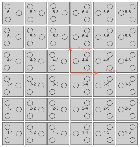
Fig. 11 : CCD numbering and location at detector plane level (Front view) from VIS FPA ICD (EUCL-SAP-ICD-6-001) issue 2.5 2014/20/10
The different extensions may appear in any order. In all extensions, pixels are delivered at the native pixel scale. All extensions have the same pixel scale and size.
When combining multiple dithered exposures from separate detectors with gaps it becomes important to assign a “confidence” to each detector pixel so that overlapping exposures can be combined and the noise level at each pixel can be correctly estimated. Many different conventions exist for producing these confidence maps.
Internally, the VIS processing function uses relative “weight maps”, which are defined as w_j \propto \frac{1}{{\sigma_{j}}^{2}}, where \sigma_j is the standard deviation (or “RMS” of the j_th pixel). Currently to meet the requirements set by other PFs, “RMS” maps are simply generated directly from the output image using SExtractor ([Bertin & Arnouts 1996]_). These maps are generated by computing the standard deviation of pixels in a sliding window on the input images, after removing objects.
Note that these RMS maps only contain a noise contribution from the background, and do not contain a contribution from the Poisson noise of each individual source. This is because combining images weighted in this way will produce a magnitude-dependent bias in the photometry of each individual source.
We will now describe the content of each extension of the calibrated VIS individual exposure:
SCI extension
The SCI extension contains calibrated pixel data for each of the VIS instrument CCDs. The individual images contain both an astrometric and photometric solution written in the FITS header. No flux scaling is applied, but the results of the photometric solution computed by VIS is written in the FITS header keywords. The astrometric solution is described as a PV projection. Images are not resampled and are delivered at the native VIS pixel scale (this means of course that instrument optical distortion is still present). The images are not background subtracted but a background map is provided as a FITS file with the same pixel size as the individual images.
RMS extension
The RMS map (described above) contains the noise at each pixel in the corresponding Science image, expressed as the absolute standard deviation.
FLG extension
The Flagmap data format is defined in the data model here and is described in human-readable format here.
Primary Header For CalibratedFrame:
SIMPLE |
/ |
||
BITPIX |
/ |
||
NAXIS |
/ |
||
EXTEND |
/ |
||
OBSTYPE |
/ |
ToFill |
|
N_CCD |
/ |
ToFill |
|
EXPTIME |
/ |
Commanded integration time in seconds, e.g. 565.0 |
|
DATAUNIT |
/ |
ToFill |
|
RA |
/ |
Commanded FPA pointing right ascension (deg) |
|
DEC |
/ |
Commanded FPA pointing declination (deg) |
|
INSTRUME |
/ |
VIS instrument |
|
SEQID |
/ |
VIS sequences as defined in EUCL-IFS-ICD-6-002 VIS Data ICD |
|
ORIENTAT |
/ |
ToFill |
|
DATE |
/ |
UT date when this file was created |
|
DATE-OBS |
/ |
UTC Date of observation (start), e.g. ‘2014-03-15T09:30:09.313’ |
|
VERSION |
/ |
ToFill |
|
END |
|||
Extension Header For CalibratedFrame:
XTENSION |
/ |
||
BITPIX |
/ |
||
NAXIS |
/ |
||
NAXIS1 |
/ |
||
NAXIS2 |
/ |
||
PCOUNT |
/ |
||
GCOUNT |
/ |
||
TIMESYS |
/ |
Time scale of the time-related keywords |
|
DATE |
/ |
UT date when this file was created |
|
MJDATE |
/ |
MJD start time, e.g. 56731.39594113 |
|
WCSAXES |
/ |
Number of coordinate axes |
|
CRPIX1 |
/ |
Reference pixel x coordinate |
|
CRPIX2 |
/ |
Reference pixel y coordinate |
|
CRVAL1 |
/ |
Right ascension at ref pixel |
|
CRVAL2 |
/ |
Declination at ref pixel |
|
CTYPE1 |
/ |
Coordinamte 1 type |
|
CTYPE2 |
/ |
Coordinamte 2 type |
|
RA |
/ |
Commanded FPA pointing right ascension (deg) |
|
DEC |
/ |
Commanded FPA pointing declination (deg) |
|
CD1_1 |
/ |
Translation matrix element |
|
CD1_2 |
/ |
Translation matrix element |
|
CD2_1 |
/ |
Translation matrix element |
|
CD2_2 |
/ |
Translation matrix element |
|
EXTNAME |
/ |
Format: CCD row-CCD column.quadrant id, e.g. 2.3-H |
|
INSTRUME |
/ |
VIS instrument |
|
EXPTIME |
/ |
Commanded integration time in seconds, e.g. 565.0 |
|
DETECTOR |
/ |
ToFill |
|
GAIN |
/ |
Maximum equivalent gain (e-/ADU) |
|
RDNOISE |
/ |
Read out Noise |
|
QE |
/ |
Quantum Efficiency |
|
DC |
/ |
ToFill |
|
PIXSIZE |
/ |
ToFill |
|
PIXSCALE |
/ |
ToFill |
|
CCDID |
/ |
e.g. Detector ID and quad, e.g. 1-1.H’ … ‘6-6.E’ |
|
QUADID |
/ |
e.g. Quadrant ID, e.g. ‘E’, ‘F’, ‘G’ or ‘H’ |
|
PRESCANX |
/ |
number of serial prescan pixels, e.g 51 |
|
OVRSCANX |
/ |
number of serial overscan pixels, e.g 20 |
|
DETSEC |
/ |
ToFill |
|
ASEC |
/ |
ToFill |
|
DSEC |
/ |
ToFill |
|
TSEC |
/ |
ToFill |
|
BSEC |
/ |
ToFill |
|
CSEC |
/ |
ToFill |
|
MAXLIN |
/ |
ToFill |
|
SATURATE |
/ |
Saturation Level (ADU) |
|
NON_LIN |
/ |
ToFill |
|
RON_STD |
/ |
ToFill |
|
BIAS_LVL |
/ |
Bias Level |
|
ADC_MAX |
/ |
ToFill |
|
PC1_1 |
/ |
Coordinate transformation matrix element |
|
PC1_2 |
/ |
Coordinate transformation matrix element |
|
PC2_1 |
/ |
Coordinate transformation matrix element |
|
PC2_2 |
/ |
Coordinate transformation matrix element |
|
CDELT1 |
/ |
[deg] Coordinate increment at reference |
|
CDELT2 |
/ |
[deg] Coordinate increment at reference |
|
CUNIT1 |
/ |
Physical units of CRVAL1 |
|
CUNIT2 |
/ |
Physical units of CRVAL2 |
|
LONPOLE |
/ |
[deg] Native longitude of celestial pol |
|
LATPOLE |
/ |
[deg] Native latitude of celestial pole |
|
RADESYS |
/ |
Astrometric system |
|
DATE-OBS |
/ |
UTC Date of observation (start), e.g. ‘2014-03-15T09:30:09.313’ |
|
CHECKSUM |
/ |
HDU checksum updated 2018-11-15T12:07:22 |
|
DATASUM |
/ |
data unit checksum updated 2018-11-15T12:07:22 |
|
NBIAS |
/ |
Number of Bias Frames |
|
COMBMETH |
/ |
Combination Method Used |
|
NORMMETH |
/ |
Normalisation Method |
|
END |
|||
Weight Map:
SIMPLE |
/ |
||
BITPIX |
/ |
||
NAXIS |
/ |
||
NAXIS1 |
/ |
||
NAXIS2 |
/ |
||
EXTEND |
/ |
||
CTYPE2 |
/ |
Coordinamte 2 type |
|
CTYPE1 |
/ |
Coordinamte 1 type |
|
CUNIT2 |
/ |
Physical units of CRVAL2 |
|
CUNIT1 |
/ |
Physical units of CRVAL1 |
|
BUNIT |
/ |
Pixel data unit, e.g. ‘electrons’ or ‘adu’ |
|
END |
|||
Background Map:
SIMPLE |
/ |
||
BITPIX |
/ |
||
NAXIS |
/ |
||
NAXIS1 |
/ |
||
NAXIS2 |
/ |
||
EXTEND |
/ |
||
CTYPE2 |
/ |
Coordinamte 2 type |
|
CTYPE1 |
/ |
Coordinamte 1 type |
|
CUNIT2 |
/ |
Physical units of CRVAL2 |
|
CUNIT1 |
/ |
Physical units of CRVAL1 |
|
BUNIT |
/ |
Pixel data unit, e.g. ‘electrons’ or ‘adu’ |
|
END |
|||